
I. Aufbau der Klimaanlage & Einführung in die Komponenten
Zusammensetzung der Klimaanlage:
Die Klimaanlagen von Kraftfahrzeugen bestehen typischerweise aus folgenden Komponenten: Kompressor, Kondensator, Trockner, Expansionsventil, Verdampfer, Gebläse, Drosselventil und Belüftungssystem.
Einführung in die Komponenten von Klimaanlagensystemen – HLK-Klimaanlagenbaugruppe:
Die Klimaanlage verfügt über Moduswahlklappen, mit denen kalte oder warme Luft gezielt zu bestimmten Auslässen wie Fußraum-, Gesichts- oder Entfrostungsdüsen geleitet wird. Temperaturregler mischen kalte und warme Luft, um die gewünschte Austrittstemperatur zu erreichen. Die Luftmischungsklappe regelt das Verhältnis von Kabinen- und Außenluft und beeinflusst so direkt Temperatur, Luftqualität und die Entfrostungs-/Entfeuchtungsfunktion.
Einführung in die Komponenten von Klimaanlagen – Kondensator:
Funktion des Kondensators: Kühlung des Kältemittels.
Der mit einem Trockner integrierte Kondensator, bei dem am Ende des Kältemittelkreislaufs innerhalb des Kondensators ein Flüssigkeitsbehältertrockner installiert ist, ermöglicht eine vereinfachte Konstruktion des Klimaanlagensystems und erhöht die Zuverlässigkeit des Kältesystems.
Einführung in die Komponenten von Klimaanlagen – Kompressor:
Der Kompressor fungiert als das „Herz“ der Klimaanlage, analog zur Rolle des Motors in einem Fahrzeug – er ist die treibende Einheit.
Bei herkömmlichen Klimaanlagen wird der Kompressor über einen Keilriemen vom Motor angetrieben.
Der Kompressor darf ausschließlich gasförmiges Kältemittel ansaugen und ausstoßen.
Sein interner Mechanismus enthält zahlreiche bewegliche Teile, weshalb ausreichend Schmieröl zur Schmierung dieser Komponenten erforderlich ist.
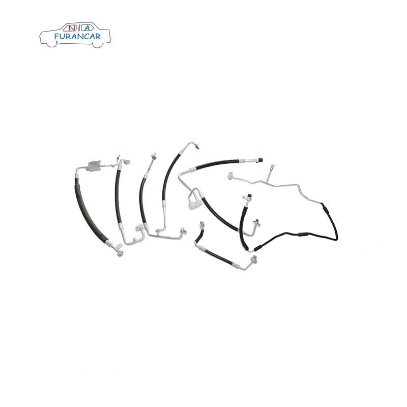
Einführung in die Komponenten von Klimaanlagensystemen – Klimaanlagenleitungen:
Das Klimaanlagen-Rohrleitungssystem besteht aus wichtigen Komponenten wie Aluminiumrohren, flexiblen Schläuchen und Rohrverschraubungen, die alle Elemente der Klimaanlage miteinander verbinden. Aluminiumrohre und flexible Schläuche werden durch Verpressen fest verbunden, wobei es je nach Modell und Hersteller zu geringfügigen Abweichungen bei den Verpressungsmaßen kommen kann. Um potenzielle Schäden durch Motorvibrationen zu minimieren, werden für die Leitungen zwischen Saug- und Druckanschluss des Kompressors flexible Gummischläuche verwendet. Ihre Flexibilität absorbiert Vibrationen effektiv, verbessert die Dichtigkeit des Systems und verlängert die Lebensdauer der Rohrleitungen. Viele Hersteller haben zudem Nylon-Klimaanlagenschläuche entwickelt, die in Serienfahrzeugen zum Einsatz kommen.
II. Kälteprinzipien von Klimaanlagen
Das Funktionsprinzip von Kälteanlagen beruht auf der kontinuierlichen Verdampfung und Verflüssigung von Kältemittel. Der gesamte Kältekreislauf umfasst vier Phasen: Kompression, Kondensation und Wärmeabgabe, Drosselung und Verdampfung. Bei der Kompression wird das vom Verdampfer aufbereitete Kältemittelgas mit niedriger Temperatur und niedrigem Druck vom Kompressor zu einem Gas mit hoher Temperatur und hohem Druck verdichtet und anschließend dem Kondensator zugeführt. In der Phase der Kondensation und Wärmeabgabe kondensiert das Kältemittelgas unter Wärmeabgabe allmählich zu einer Flüssigkeit. Die anschließende Drosselung mittels des Expansionsventils bewirkt die Druckreduzierung des Kältemittels. Schließlich findet im Verdampfer die Verdampfung statt, bei der das Kältemittel einen erheblichen Teil der Wärme aufnimmt, bevor es wieder in den Kompressor eintritt und so den Fahrzeuginnenraum kühlt.
III. Vorsichtsmaßnahmen für die Kältemittelleitungsbaugruppe von Klimaanlagen
Bei der Installation von Klimaanlagenleitungen und dem Verbinden von Komponenten ist die Art und Weise des Zusammenfügens und Festziehens der Verbindungen von entscheidender Bedeutung.
Beim Entfernen von Rohrstopfen ist zunächst der O-Ring auf Unversehrtheit zu prüfen und die Dichtfläche gleichmäßig mit Schmiermittel zu bestreichen. Bei Gewindeverbindungen ist das Schmiermittel auch gleichmäßig auf das Außengewinde aufzutragen. Beim Auftragen des Schmiermittels sind folgende Punkte zu beachten:
Als Schmierstoff muss ein Kompressorenschmierstoff, PAG oder ein gleichwertiger Schmierstoff verwendet werden.
Um ein Festfressen nach dem Anziehen zu verhindern, sollten die Gewindeabschnitte eingefettet werden.
Um die Aufnahme von Feuchtigkeit zu verhindern, sollten Schmierstoffbehälter nach Gebrauch umgehend wieder verschlossen werden.
Um die Sauberkeit von Systemkomponenten wie Rohrleitungen zu gewährleisten, entfernen Sie die Stopfen erst unmittelbar vor der Installation. Setzen Sie sie umgehend wieder ein und lassen Sie sie nicht über längere Zeit der Luft ausgesetzt.
Klemmverbindung: Die geschmierte Klemmplatte mit der Sackbohrung senkrecht durch den Doppelbolzen führen. Gleichzeitig das Klemmgelenk senkrecht in die entsprechende Montagebohrung einsetzen. Beim Einsetzen ein Verkanten vermeiden, um Beschädigungen des O-Rings zu verhindern. Sobald die Flächen parallel zueinander stehen, die Mutter handfest anziehen, bis ein Widerstand spürbar ist. Anschließend die Schraube mit einem Drehmomentschlüssel oder einer Ratsche auf das vorgeschriebene Drehmoment anziehen und die Position markieren. Das Anzugsmoment für M8-Muttern beträgt 15–20 Nm, für Expansionsventilmuttern (M6) 6–10 Nm.
Gewindeverbindung. Den mit Schmiermittel versehenen Dichtring in das Gewinde einsetzen. Ausrichten und senkrecht einführen, bis die Vorderseite des Stopfenkopfes das Gewinde berührt. Die Mutter handfest anziehen und anschließend das Gewinde mit einem Gabelschlüssel sichern. Die Mutter mit einem Drehmomentschlüssel festziehen und die Position markieren (siehe Abbildung unten). Anzugsmomente: Hochdruck-Rohrverschraubung (M16×1,5 Gewinde): 12–15 Nm; Niederdruck-Rohrverschraubung (M24×1,5 Gewinde): 30–35 Nm.
Hinweis: Beim Festziehen von Gewindeverbindungen ist es unbedingt erforderlich, zwei Schraubenschlüssel gleichzeitig zu verwenden, um eine Verformung der Rohrleitung zu vermeiden.
Verbindung der Doppelklemmgelenke. Zuerst das Ende der Hochdruckklemme in die Gabelnut der Niederdruckklemme einführen. Die Kompressorschnittstelle ausrichten und parallel zusammendrücken. Sobald die Klemmen flach anliegen, die Position des O-Rings auf Fehlausrichtung oder Herausdrücken prüfen. Die Schrauben handfest anziehen, bis ein Widerstand spürbar ist. Anschließend mit einem Drehmomentschlüssel oder einer Ratsche auf das vorgeschriebene Drehmoment anziehen und die Position markieren (siehe Abbildung unten). Das Anzugsmoment für die Kompressor-Endschrauben (M10×1,25×35) beträgt 20–30 Nm.
Ergänzende Hinweise zur Installation von Klimaanlagenrohren:
Geringfügige Beschädigungen der O-Ringe während der Rohrinstallation können die Dichtheit beeinträchtigen und zu Kältemittelleckagen führen.
Prüfen Sie nach der Installation, ob die Rohre die umliegenden Fahrzeugkomponenten nicht behindern oder sich frei bewegen können. Beheben Sie jegliche Reibung oder Behinderung umgehend durch Justierung und sichern Sie Rohre, die sich frei bewegen können, mit geeigneten Befestigungsmitteln.
Bewegliche Bauteile wie der Gaszug und der Ölmessstab dürfen niemals zusammen mit Klimaanlagenleitungen verlegt werden. Dies verhindert den Abrieb der Klimaanlagenleitungen, der zu einem Kältemittelaustritt führen könnte.
Stichworte :


 Whatsapp :
  Telefon :
  Email :