
Bei der Konstruktion müssen neben den Fertigungsprozessen auch die Montagefreundlichkeit für OEMs berücksichtigt werden. Während der Testproduktionsphase eines neuen Automobilmodells traten häufig Montageschwierigkeiten bei den Kältemittelleitungen der Klimaanlage auf, was später zu erheblichen Nachkonstruktionskosten führte. Durch die Anwendung von synchronem Engineering für die Endmontage wurden virtuelle Montageanalysen und Konstruktionsbeschränkungen bereits bei der Entwicklung der Kältemittelleitungen berücksichtigt. Dieser Ansatz reduzierte die Produktionskosten in der Endmontage effektiv und steigerte die Fertigungseffizienz. Dieser Artikel beschreibt die Montage- und Konstruktionsherausforderungen, die bei der synchronen Engineering-Analyse für Kältemittelleitungen der Klimaanlage auftraten, sowie entsprechende Lösungsansätze. Er bietet wertvolle Hinweise für die Entwicklung von Kältemittelleitungssystemen in neuen Fahrzeugmodellen.
Einführung in die Synchrontechnik für die Endmontage
Synchrones Engineering (SE) für die Endmontage bezeichnet den Prozess, bei dem Endmontageprozesse parallel in die Konstruktions- und Entwicklungsphasen der Automobilentwicklung eingebunden werden. Es umfasst primär die Prozessanalyse digitaler Montagemodelle, Produktionslinien, Anlagen und Montageverfahren und liefert dem Konstruktionsteam so realisierbare Prozessoptimierungen. Hauptziel ist die Identifizierung und Behebung potenzieller Probleme im Produktdesign während der Zeichnungserstellung und der Generierung digitaler Modelle. Dies ermöglicht proaktive Maßnahmen gegen potenzielle Probleme bei der Prozessimplementierung und gewährleistet die Produktionsfähigkeit und Anlagen-/Werkzeugkompatibilität neuer Fahrzeugmodelle.
Rohrleitungsbaugruppe und -konstruktion für Klimaanlagen
1. Zusammensetzung des Kältemittelleitungssystems der Klimaanlage im vorderen Fahrgastraum von Kraftfahrzeugen
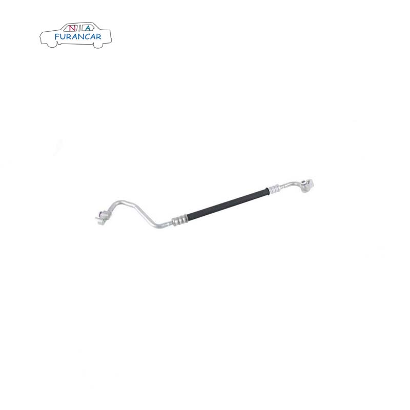
Die Kältemittelleitungen der Klimaanlage bestehen im Wesentlichen aus der Hoch-/Niederdruck-Rohrleitungseinheit der Klimaanlage, der Abgasrohreinheit II der Klimaanlage, der Abgasrohreinheit I der Klimaanlage (die je nach Montagemöglichkeit mit Einheit II integriert werden kann), der Niederdruck-Rohrleitungseinheit I der Klimaanlage und der Hochdruck-Rohrleitungseinheit I der Klimaanlage (die je nach Montagemöglichkeit mit der Hoch-/Niederdruck-Rohrleitungseinheit integriert werden kann).
2. Konstruktions- und Montageprobleme bei Kältemittelleitungen für Klimaanlagen
(1) An der Verbindungsstelle zwischen den Hoch-/Niederdruckleitungen und dem Expansionsventil der Heizungs-, Lüftungs- und Klimaanlage sind die in die Hoch-/Niederdruckleitungen integrierten Schaumstoffdichtungen übermäßig dick und starr. Dies führt zu erheblichen Beeinträchtigungen der Frontplatte und erschwert die Montage der Leitungen.
(2) Die Hoch-/Niederdruck-Rohrleitungsbaugruppe der Klimaanlage verfügt über eigene Montagehalterungen (befestigt an den Rumpfseitenwänden und Längsträgern). Die Befestigungslöcher sind kreisförmig und bieten nicht genügend Spielraum für einen Versatz entlang der X-Achse. Aufgrund der erforderlichen Passgenauigkeit und der sich ergebenden Toleranzen kann es zu Abweichungen bei der Ausrichtung der Schraubenlöcher kommen.
(3) Die Kältemittelleitungen der Klimaanlage sind mittels Schrauben und Muttern verbunden. Während der Prototypenphase kann der Platz zum Anziehen von Werkzeugen (wie z. B. Schlagschraubern) unzureichend sein. Auch bei Verwendung kurzer Steckschlüssel als Ersatzwerkzeug besteht weiterhin eine Behinderung.
(4) Bei der Montage der Rohrverbindungs-Klemmplatte kann kein Kältemittelöl aufgetragen werden, was nach der Fertigstellung zu Kältemittelleckagen führt. Die Verbindung zwischen den Hoch- und Niederdruck-Rohrleitungen der Klimaanlage weist keinen flexiblen Schlauchabschnitt auf, wodurch eine starre Rohrverbindung schwierig und anfällig für Verformungen ist.
(5) Die Rohrleitungsführung ist suboptimal, was häufig zu Problemen wie ungewöhnlichen Geräuschen und mangelhafter Montage führt. Beispielsweise verläuft die Rohrleitungsführung nicht ausreichend eng am Motorraum entlang, und die Einfüllöffnung der Klimaanlage ist zu tief positioniert, um ein Nachfüllen zu ermöglichen.
3. Konstruktionsbeschränkungen für Kältemittelleitungen in Klimaanlagen
Konstruktionsvorgaben sind verbindliche Spezifikationen, die sich aus der Zusammenstellung wiederkehrender Probleme bei der Einführung und dem Prototyping neuer Fahrzeugmodelle ergeben. Sie dienen dazu, Bereiche zu identifizieren, die in nachfolgenden Produktkonstruktionen verbessert werden müssen. Als Reaktion auf die zuvor genannten Montageprobleme wurden die folgenden Konstruktionsvorgaben festgelegt:
(1) Das Schaumstoffmaterial in der Druckplatte am Verbindungspunkt zwischen der Hoch-/Niederdruck-Klimaanlagenrohrleitung und dem HLK-Expansionsventil ist als PUR-Material mit einer Dicke von vorzugsweise weniger als 15 mm vorzusehen.
(2) An der Halterung der Hoch-/Niederdruck-Rohrleitungsbaugruppe der Klimaanlage müssen alle Befestigungslöcher außer dem primären Positionierungsloch in X-Richtung elliptisch sein (z. B. 8 × 10 mm, abhängig von den Schraubenspezifikationen), um die Gesamttoleranzen zu berücksichtigen. Die Befestigungspunkte der Halterung an der Fahrzeugkarosserie müssen Verdrehsicherungen (z. B. Sicherungsclips) aufweisen, um ein Verdrehen der Halterung beim Anziehen der Schrauben und damit eine Verformung des Kanals zu verhindern. Die Halterungen der Klimaanlagenkanäle müssen an starren Rohrabschnitten angebracht werden, um ein Verkratzen der flexiblen Schläuche zu vermeiden.
(3) Bei der Auslegung der ersten Daten muss der erforderliche Spielraum zum Anziehen von Rohrverbindungen berücksichtigt werden. Bei Verwendung einer Winkelnietpistole muss der Nietkopf mehr als 85 mm vom Bolzenende entfernt sein; bei Verwendung einer geraden Nietpistole muss der Nietkopf 40 mm vom Bolzenende entfernt sein.
(4) Bei Rohrverbindungen muss das Außengewinde in Z-Richtung nach oben zeigen (in X-Richtung ist dies nicht erforderlich), um das Einfüllen von Kältemittelöl zu erleichtern. Starre Rohre dürfen nicht direkt miteinander verbunden werden; eine Verbindung muss einen flexiblen Schlauchübergang aufweisen. Die Abdichtung der Verbindung muss fachgerecht erfolgen, beispielsweise durch Anbringen einer Dichtung.
(5) Oberhalb der Hoch- und Niederdruck-Füllanschlüsse der Klimaanlagen-Rohrleitungsbaugruppe muss ein Freiraum von 50 mm Durchmesser und 250 mm Höhe ohne Hindernisse gewährleistet sein. Darüber hinaus muss der Abstand zwischen den Hoch- und Niederdruck-Füllanschlüssen entsprechend der Größe der Füllpistolendüse bemessen sein.
Abschluss
Dieser Artikel fasst häufige Probleme zusammen, die bei der Endmontage von Kältemittelleitungen für Kfz-Klimaanlagen auftreten. Durch die Anwendung von Simultaneous Engineering in den frühen Phasen der Einführung neuer Modelle konnten Systemanalyse-Beschränkungen in die Konstruktionsphase integriert werden. Dieser Ansatz minimierte Mängel im Produktdesign, optimierte die Fertigung der Endmontageprozesse und senkte die Produktionskosten des Unternehmens. Darüber hinaus bietet er wertvolle Hinweise für die Entwicklung von Kältemittelleitungen in zukünftigen Fahrzeugmodellen.


 Whatsapp :
  Telefon :
  Email :